How to Select the Correct Data Cable for Your Industrial Application
In this article, you will learn what the most common mistakes are when selecting Industrial Ethernet and bus cables and how to avoid them.
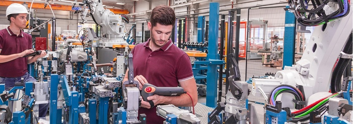
All cables and wires that contribute to communication in any way are commonly referred to as data cables. However, there are significant differences such as the multitude of structures including copper and fiber optics, for example. Copper data cables come in many different types: low-frequency, coaxial, telephone, and bus cables, diverse Ethernet systems, or microwave cables for special applications that require gigahertz transmission rates. Selecting the wrong cable can quickly lead to costly disruptions and errors.
In general, data cables are low-capacity cables. This means that there is as little electrical energy accumulated in the cable as possible when transferring data due to the negative impact it has on signal quality. The capacity is partially dependent on the cable’s insulation material. Modern bus and Ethernet cables primarily use materials such as polyethylene (PE) or polypropylene (PP), which provide especially good insulation due to their dielectric constants (εr). The lower this value is, the better the material is at insulating, and the lower the capacity of the cable. This is why thinner insulation can be used when the same dielectric strength is required.
A Comparison of Cable Insulation Materials
| Material | VDE Label | Dielectric Constant | Halogen Free |
| PVC | Y | 3.6-6 | No |
| PVC +90°C | Yw | 4-6.5 | No |
| PE | 2Y | 2.3 | Yes |
| PE foam | 02Y | 1.6-1.8 | Yes |
| PP | 9Y | 2.3-2.4 | Yes |
| PP foam | 1.6-1.8 | Yes | |
| PUR | 11Y | 4-7 | Yes* |
| FEP | 6Y | 2.1 | No |
| *Dependent on the flame retardants used | |||
Pristine data transmission is achieved through the correct cable construction. A solid wire, which is perfectly round and has a uniform diameter, offers the best electrical performance. For Industrial Ethernet and bus cables, construction according to the American Wire Guage (AWG) is preferred since this flexible construction results in a round conductor. Metric cables are not suitable for this application since they have a bunched construction and are not round. This results in variable capacities which heavily impair high-frequency data transmission.
Common Errors When Selecting Industrial Ethernet and Bus Cables
1. Low-Frequency Cables for High-Frequency Applications
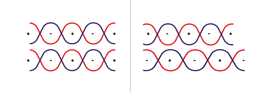
Selecting low-frequency cables for high-frequency Ethernet connections is a common cause of malfunctions in data transmission. These cables are also low-capacity but exhibit a different characteristic impedance from what is required by the Ethernet standard. This results in a mismatch or discontinuity. In low-frequency data cables, all pairs are laid in parallel strands. This means that all four lay lengths are the same. Ethernet cables used in high-frequency applications must also be optimally decoupled. This is achieved by using four different lay lengths, which are individually measured. The positions of the twisted pairs within the overall construction must also be taken into account.
2. Classic Pair Stranding Instead of a Star Quad
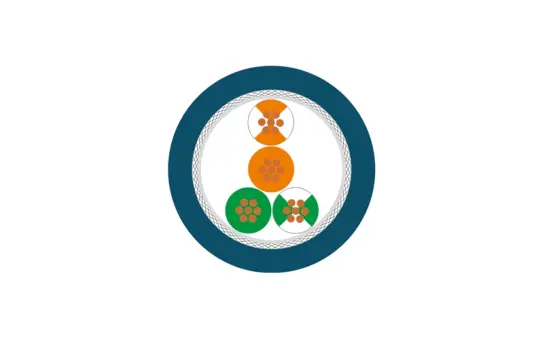
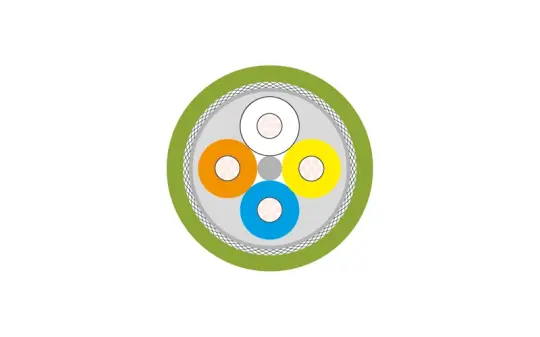
Many industrial communications standards, such as PROFINET, EtherCAT, or SERCOS III, use cables with two twisted pairs, which are twisted into what is called a star quad, for data transmission. Here, all four conductors are stranded in a perfectly round shape. The benefit of this is that it leads to no differences in transit time. This differs from the classic pair stranding, where the individual twisted pairs must have two different stranded lay lengths due to the required decoupling. If the incorrect twisted-pair cable is used, it could lead to problems with transmission and transit times.
2 Pairs
- 4 x Conductor diameter
- 3 x Stranding
- Pairs according to illustration
- Straight forward
- Different signal transit times
Star Quad
- 2.4 x Conductor diameter
- 1 x Stranding
- Diagonal conductors create the electrical pair: white/blue and orange/yellow
- Identical signal transit times
In star quads, the conductors that are diagonally opposite from each other form the electrical pair. If this rule is ignored when connecting the cable, the characteristic impedance and the near-end crosstalk (NEXT) of the cable are changed, which may reduce the transmission quality, as well. Even shielded, four-conductor sensor cables are not suited for use as high-frequency Industrial Ethernet or bus cables, despite their construction appearing comparable at first glance. The difference is that the conductor insulation strength is not intended for Ethernet, and the stranding is not perfectly round in construction. This results in an inadequately functioning cable due to unsuitable characteristic impedance, NEXT and cable attenuation.
3. Too Long of Cable or Too Small of Diameter
Another classic example is cable segments that are too long. According to the Ethernet standard, the maximum cable length before a repeater must be used is 328 feet (100 meters). This device receives the weak signal and transmits it again at full strength. In practice, segments with lengths longer than 328 feet (100 meters) can be found, however, these are not in compliance with the applicable standards. In these cases, rising temperatures, aging and other factors could quickly lead to defects or failures. Thinner cables with AWG 26 diameters are limited to 197 – 230 feet (60 - 70 meters). It is important to remember that every connector is a joint that causes loss via attenuation and reflection, which reduces the range.
4. Incorrect Connector
It is a common occurrence that non-standard and untested connectors are used in Ethernet applications, such as D-Sub or M12 plugs, which are A-coded with an 8-pin design. These connectors do transmit data, however the quality is significantly reduced due to the lower near-end crosstalk (NEXT). The reason for this is the positioning of the middle pin, which does not comply with standards and impedes data transmission.
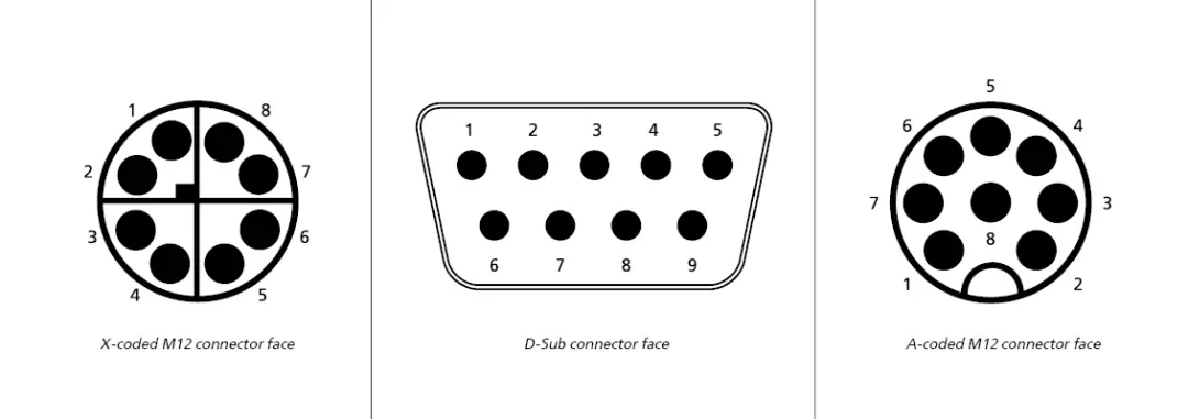
According to Ethernet standards, admissible mating faces for the best data cabling are shielded connectors (male plugs/ female sockets):
- RJ45 4-pin (100 Mbit 4-pin)
- RJ45 8-pin (Gbit 8-pin)
- D-coded M8 & M12 (100 Mbit)
- A-coded M8 4-pin (100 Mbit)
- P-coded M12 (100 Mbit)
- X-coded M12 (Gbit)
- ix Industrial (Gbit)
- Mini I/O
- Single Pair Ethernet (SPE)
Furthermore, there are varying standards such as PROFINET, EtherCAT, or Single Pair Ethernet (SPE) that can transmit data and power in one hybrid plug. These either adhere to IEC norms, have been evaluated by the appropriate organizations, or are being standardized.
Standardized Hybrid Ethernet Plugs
- M8 SPE acc. to IEC 63171-6
- M12 SPE acc. to IEC 63171-7
- Y-coded M12 acc. to IEC 61076-2-113
- M23 acc. to IEC 61076-2-117
- RJ45 Hybrid acc. to IEC 61076-3-106
- ix Industrial acc. to IEC 61076-3-124
Certain connector manufacturers have their own hybrid solutions in their portfolios that are not standardized but have been tested and evaluated for Ethernet conformity. As a basic principle, it is suggested to always stick to standardized and evaluated Ethernet connectors.
Take away:
When selecting data cables for industrial applications, users should adhere to the appropriate standards in order to prevent failures and malfunctions. Users must also pay attention to the lengths of the individual segments, the number of connectors, and the different diameters of installation and patch cables. Furthermore, the aging of individual components can lead to a reduction in the transmission quality and interruptions, in the long term. With 45 years of experience, HELUKABEL is an expert in connection technology and is happy to support users in identifying the perfect Industrial Ethernet or bus cables for their industrial application.
